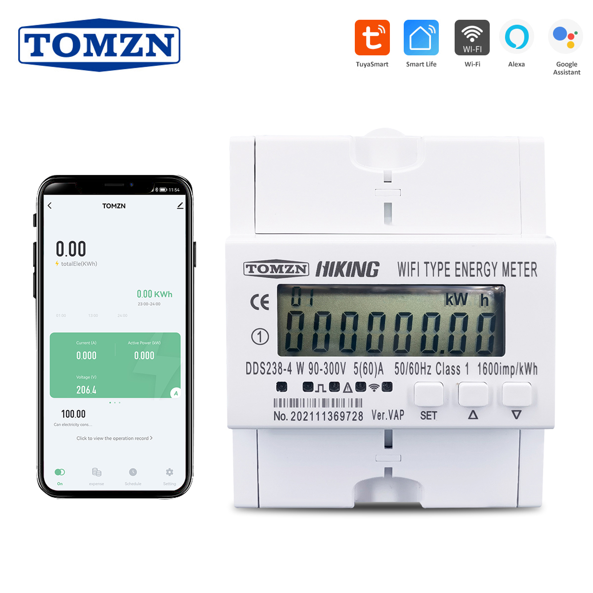

Function: 1. On/off Switch 2. Time Relay Switch 3. Real voltage display on app 4. Real Current display on app 5. Real active power display on app 6. Kwh display on app 7. kwh prepayment function. 8. Over current protection, over and under voltage protection, Max power protection, min power protection. 9. RS485 port: MODBUS-RTU protocol, 1200~9600bps,None parity ,default 9600bps 1. General Description DDS238-4 W type multi-function protective smart energy meter is designed to measure single phase two wire AC active energy and variable parameter. The meter have RS485 communication port and WIFI communication, it can use APP for remote reading and control on/off. All of its functions comply with the relative technical requirement for class 1 single phase watt hour meter in IEC62053-21 and its data communication rules obey the requirement of MODBUS-RTU and WIFI 802.11b/g/n.It is a long life meter with the advantage of high stability , high over load capability , low power loss and small volume . The meter should be installed in suitable environment with ambient temperature range between -25 ℃ ~ 55 ℃ ,the relative humidity less than 75% and temperature limits between and -40 ℃ ~ 70 ℃ . The meter is manufactured complying with international standard IEC62052-11 on “Electricity metering equipment (AC) General requirements tests and test conditions” and IEC62053-21 on “Static meters for active energy (classes 1 and 2)”. 2.Specification and Technical Parameters 2.1Specification Meter type DDS238-4 W VAP Rate frequency 50 or 60 Hz Rated current 5(60)A Rate voltage 120V / 220V / 230V /240V (90~300V) Normal voltage range 90%Un~110%Un Limits voltage range 70%Un~120%Un kWh Accuracy Class 1 R.M.S accuracy Class 0.5 Pulse constant See meter RS485 port MODBUS-RTU protocol, 1200~9600bps,None parity ,default 9600bps WIFI 802.11b/g/n ,only support 2.4GHz network , not support 5GHz network 2.2 basic parameters Delayed recovery after protection 60s(default)1~512s overvoltage / undervoltage / overload event judgment time 3s (default)0.1~60s Overvoltage protection value 270V 1(default),APP can set value Overvoltage recovery value 260V 1(default)= (APP overvoltage value – 10V) Undervoltage protection value 170V 1(default),APP can set value Undervoltage recovery value 180V 1(default)= (APP overvoltage value 10V) Overload protection value 65A (default), 10~65A APP can set value Delay on/off control 00:01—24:00 Hour Note: when it happens interrupt power-supply (power grid off ), the meter will not cut off , undervoltage event must last 3s , then it will cut off. 2.2 Technical Parameters 2.2.1 Basic tolerance Load current(A) Power factor (CosΦ) Basic error(%) 1.0 class 2.0 class 0.05Ib 1.0 1.5 2.5 0.1Ib—Imax 1.0 1.0 2.0 0.1Ib 0.5(lag) 1.5 2.5 0.8(advanced) 1.5 02Ib—Imax 0.5(lag) 1.0 2.0 0.8(advanced) 1.0 2.2.2 Self-consumption Current circuit is less than 1.5VA Voltage circuit is less than 2W/8VA 2.2.3 Starting current Under the rated voltage , rated frequency and COSΦ=1 , the meter shall start and continue to register on application of 0.2% In (if CT is used) or 0.4% Ib . 2.2.4 A nti-creeping The meter has anti-creeping logical circuit. When 115%Un is connected to the meter and current circuit is cut , the meter shall not create more than one pulse in a stipulated time 2.2.5 A verage-life The meter can be used for at least 10 years in normal operation specified in this manual 2.2.6 LCD: 6 2 (999999.99kWh) 3.Basic Features 3.1 Measuring positive & negative active energy with negative energy accumulated into positive energy 3.2 The meter display total active energy, positive active energy , negative active energy , total reactive energy , balance active energy 3.3 The meter also display real voltage , real current , real active power , real power factor , real frequency 3.4 Pulse LED indicates working of meter,Pulse output with optical coupling isolation . 3.5 RS485 communication port and WIFI communication 3.6 Measuring active energy without calibration under long term operation 3.7 Display step by step with button 3.8 APP can display total active energy, balance active energy, real voltage , current ,active power and remoter control on/off. 3.9 Hour/Day/Month/Year history active energy consumption tracking by APP 3.9 It has overvoltage and undervoltage protection , it can set value from APP and by button Each protection function can be opened/closed as customer requirement 3.10 It has overload protection ,it can set value from APP 3.11 Voice control on/off function 3.12 Alarm event records on APP 3.13 Prepayment function, if balance energy used up. It will cut off automatic. This function can be opened/closed by APP 3.14 Energy data can store on memory chip when power off, it also still measure energy whenlose WIFI connection and it will update the energy on APP when connect WIFI again 3.15 It can control on/off by hand with button when prepayment function close 3.16 It has timing control function , it can set value from APP 3.17 It can reset the active energy to zero from APP 4.Working principles Single phase voltage and current are sampled from respective sampling circuit and transformed into suitable signal, which is carried into integrated circuit , then the meter output pulse signal in positive appropriation to measured power to drive step-motor counter or LCD counter to realize energy measurement. The meter has energy pulse output for testing with pulse width of 80 20ms 9. Frame format 9.1 Read command(function code 03) Send frame Meter ID Function code Register address Data number Check code (CRC) 1byte 1byte 2byte 2byte 2byte Receive frame Meter ID Function code Data length n Data area Check code (CRC) 1byte 1byte 1byte n byte 2byte 9.2 Write command(function code 10) Send frame Meter ID Function code Register address Data number Data length n Data area Check code (CRC) 1byte 1byte 2byte 2byte 1byte n byte 2byte Receive frame Meter ID Function code Register address Data number Check code (CRC) 1byte 1byte 2byte 2byte 2byte 9.3 Energy meter register address Register address Data number Data item Data format Data unit 0x0000 2 Total kWh XXXXXX.XX kWh 0x0001 0x000C 2 Reactive kvarh XXXXXX.XX kvarh 0x000D 0x0008 2 Export kWh XXXXXX.XX kWh 0x0009 0x 000A 2 Import kWh XXXXXX.XX kWh 0x000B 0x0016 1 Voltage XXX.X V 0x0019 1 Current XX.XX A 0x001E 1 Active power XXX.XXX kW 0x002B 1 Power factor X.XXX 0x0011 1 frequency XX.XX Hz 0 x0033 1 Relay 1 means power on, 0 means power off 0x0015 1 ID baud rate First byte is ID号,the second byte is baud rate,01~04 is means Respectively 9600、4800、2400、1200 Note 1: one register address is store 2 byte data ,so the data length read as 4 byte when data number is 2 . Note 2::you can use ID ID(0x00) to broadcast and got data when you do not know the meter ID. But this ways is only for 1 pcs meter to connection on RS485 wire 10. Display item Uo Overvoltage protection value 270V 300 V 100 V If the value exceed the range , the LCD will display off and closed this protection function UoH Overvoltage recovery value 265 V 300 V 85 V This value must be smaller than overvoltage protection value. or it will default set as overvoltage protection value -5V when you save UL Under voltage protection value 170 V 300 V 85 V If the value exceed the range , the LCD will display off and closed this protection function ULH Under voltage recovery value 175 V 300 V 85 V This value must be smaller than under voltage protection value. or it will default set as under voltage protection value 5V when you save SU overvoltage / under voltage fault judgment time 3s 60s 0.1s It means the fault must be last how many times then it will make output load switch off when happen fault Io Over current protection value 60A 60 A 1 A If the value exceed the range , the LCD will display off and closed this protection function SI Over current fault judgment time 3s 60s 0.1s It means the fault must be last how many times then it will make output load switch off when happen fault SH Delay time setting for recovery load after output load switch off protection 60s 512s 1s It means the product must wait for how many times then make the output switch on again after happen protection